control valve,Electric contrPneumaticol valve,Pneumatic ball valve-Control valve manufacturer


Mobile:+86-17717520739
Wechat:17717520739
Email:info@shxvalve.com
Address: NO.720, Suide Road, Jiading District,Shanghai, China.




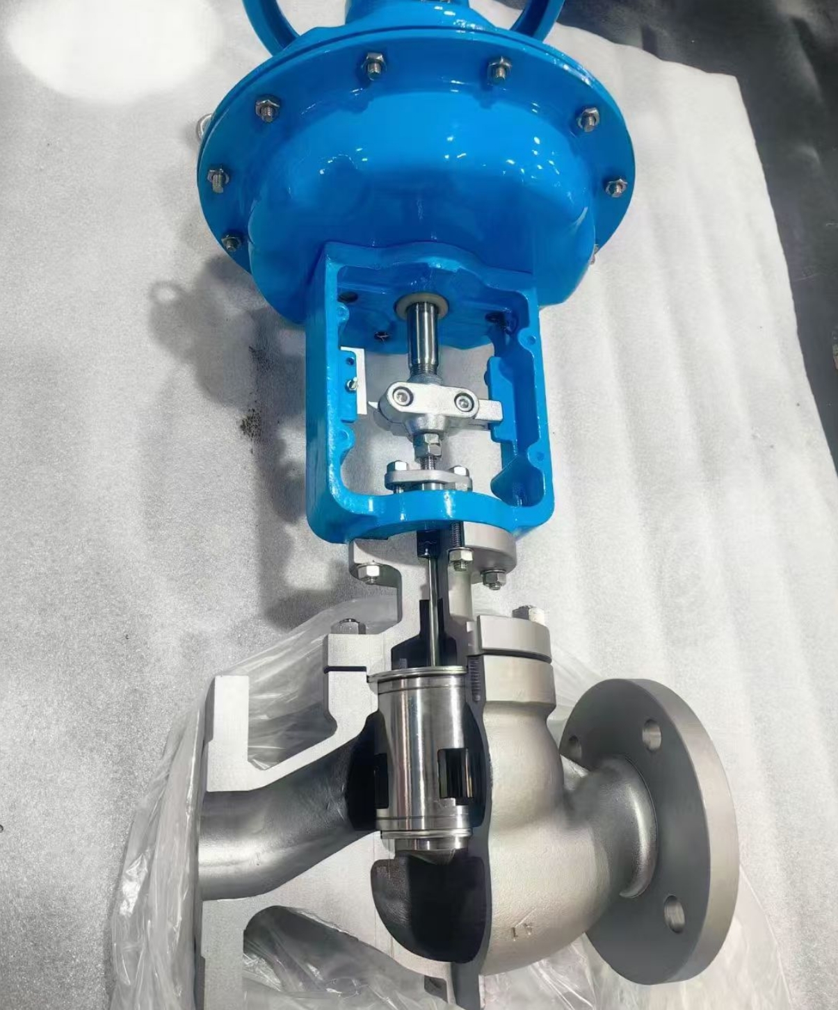

Model:
ZJHM pneumatic caged control valve is a linear-stroke automatic regulation device composed of a multi-spring pneumatic diaphragm actuator and a sleeve-type pressure-balanced valve body. ZJHM pneumatic caged control valve is different from traditional single-seat control valves that rely on plug and seat matching for flow regulation, its core feature is the adoption of a fixed sleeve throttling structure. Precision throttling windows with specific flow characteristics are prefabricated on the sleeve wall, and the valve plug moves linearly along the sleeve inner wall to change the overlapping area of throttling windows, so as to realize fluid flow regulation. Benefiting from the pressure balance design of the sleeve structure, the medium pressure acts on the upper and lower ends of the valve plug simultaneously, greatly offsetting the fluid unbalanced force.
As a core terminal execution unit of industrial automatic control systems, ZJHM pneumatic caged control valve receives standard 4–20mA electric signals or 20–100kPa pneumatic signals to convert pneumatic energy into mechanical displacement. ZJHM pneumatic caged control valve can stably adjust process parameters such as pipeline flow, pressure, temperature and liquid level. Adhering to intrinsic explosion-proof performance of pneumatic drive, it is suitable for flammable, explosive, high-temperature, high-pressure and high-differential-pressure harsh working conditions. Compared with ordinary single-seat valves, it has wider working condition adaptability and higher operational stability, and has become the preferred regulation equipment for medium and large-diameter, high-differential-pressure process systems.
ZJHM pneumatic caged control valve is an upgraded high-performance fluid regulation device optimized on the basis of traditional single-seat valves. Its core pressure balance mechanism and full-wrap sleeve guiding structure solve the technical pain points of ordinary control valves such as poor high-differential-pressure adaptability, easy vibration and unstable regulation. With the comprehensive advantages of stable performance, high regulation precision, strong working condition adaptability and high safety, ZJHM pneumatic caged control valve has become the key core equipment for fluid regulation in complex process systems such as petrochemical, power and metallurgy.
With the continuous upgrading of industrial automation and intelligent manufacturing technology, ZJHM pneumatic caged control valve will continue to make breakthroughs in structural optimization, material innovation and intelligent matching. Through scientific type selection, standardized installation and standardized whole-life maintenance, the equipment can give full play to its superior regulation performance, provide stable, efficient and safe technical support for modern industrial process production, and have broad application value and sustainable development prospects in the field of industrial automatic control.
ZJHM pneumatic caged control valve Structural Composition
The complete pneumatic sleeve control valve integrates a pneumatic actuator, sleeve-type valve body assembly and professional auxiliary accessories. The overall structure follows IEC international standards, featuring compact layout, standardized assembly and convenient disassembly and maintenance. Each functional module cooperates mutually to ensure stable signal response, accurate stroke execution, reliable fluid throttling and long-term sealing performance.
1 Pneumatic Actuator Assembly
The mainstream supporting power unit is a multi-spring pneumatic diaphragm actuator, which is superior to traditional single-spring actuators in structural design. It features small volume, light weight, stable output thrust and excellent linear signal matching, and can meet the stroke driving requirements of high-differential-pressure working conditions. Individual high-load working conditions are equipped with piston pneumatic actuators to provide larger driving thrust.
The multi-spring diaphragm actuator consists of upper and lower membrane covers, rubber elastic diaphragm, multi-group symmetric reset springs, spring seat, guide push rod and air source interface. The symmetric spring layout ensures uniform stress during reset movement, effectively avoiding stroke deviation and jamming. The flexible diaphragm divides the inner cavity into a closed air pressure chamber and a spring reset chamber. When compressed air enters the air pressure chamber, pressure difference pushes the diaphragm and push rod to move linearly; when air pressure drops, the symmetric springs drive the push rod to reset steadily, realizing bidirectional stable stroke adjustment.
Consistent with industrial universal standards, actuators are divided into air-to-open (fail-close) and air-to-close (fail-open) types. The fail-close type automatically cuts off fluid flow when the air source fails or power is lost, which is suitable for safety priority working conditions; the fail-open type maintains pipeline circulation under failure state, applicable to process systems that prohibit shutdown and emptying.
2 Core Caged-Type Valve Body Assembly
ZJHM pneumatic caged control valve body assembly is the key to distinguish sleeve valves from ordinary single-seat valves, including valve body, fixed sleeve, pressure-balanced valve plug, valve stem, bonnet and high-performance packing sealing components. The overall flow channel adopts an optimized S-shaped streamlined design, which minimizes fluid turbulence and pressure drop loss and improves medium circulation efficiency.
The fixed precision sleeve is the core throttling component of the valve. Different flow characteristic windows (linear, equal percentage, quick-opening) are precisely machined on the sleeve outer wall. The sleeve is fixed inside the valve body through positioning steps, maintaining absolute static state during valve operation. The valve plug is tightly fitted with the sleeve inner wall and moves up and down linearly along the sleeve for full-stroke guidance. This full-wrap guiding structure greatly increases the guiding area, effectively resisting fluid impact and vibration, and solving the jitter and unstable regulation problems of ordinary valves under high-flow impact.
The valve plug adopts an integrated pressure-balanced structural design. The upper and lower end faces of the plug communicate with the medium flow channel, so that the medium pressure acts on both ends to offset the unbalanced force. This design greatly reduces the driving force required for valve action, enabling the valve to adapt to ultra-high differential pressure working conditions with small-thrust actuators. The matching sealing structure is divided into metal hard seal and PTFE soft seal: the soft seal achieves zero leakage shut-off for clean media, while the metal hard seal adapts to high-temperature, high-pressure and wear-containing media.
The bonnet is designed in standard, high-temperature extension and low-temperature cold insulation types. The extended bonnet isolates extreme-temperature media from the actuator and packing components, preventing high-temperature aging and low-temperature frosting air leakage. The packing box is filled with graphite and reinforced PTFE composite packing, which ensures long-term stem tightness under frequent stroke movement and high-pressure working conditions.
3 Supporting Auxiliary Accessories
To realize automatic precise regulation and remote monitoring, ZJHM pneumatic caged control valve is usually matched with complete accessory systems. The intelligent valve positioner is the core accessory, which eliminates spring hysteresis and mechanical friction errors through closed-loop feedback calibration, improving positioning accuracy up to ±0.3% FS. The air filter regulator stabilizes air source pressure and filters moisture and impurities to ensure clean and stable power air supply.
Supporting accessories also include emergency solenoid valves, stroke limit switches, handwheel mechanisms and air storage tanks. The solenoid valve realizes rapid emergency cut-off of the valve under system failure; the limit switch feeds back full-open and full-close state signals to the DCS system for remote monitoring; the handwheel mechanism provides manual emergency regulation function when the pneumatic system fails, improving equipment operation safety and redundancy.
ZJHM pneumatic cage control valve Structure
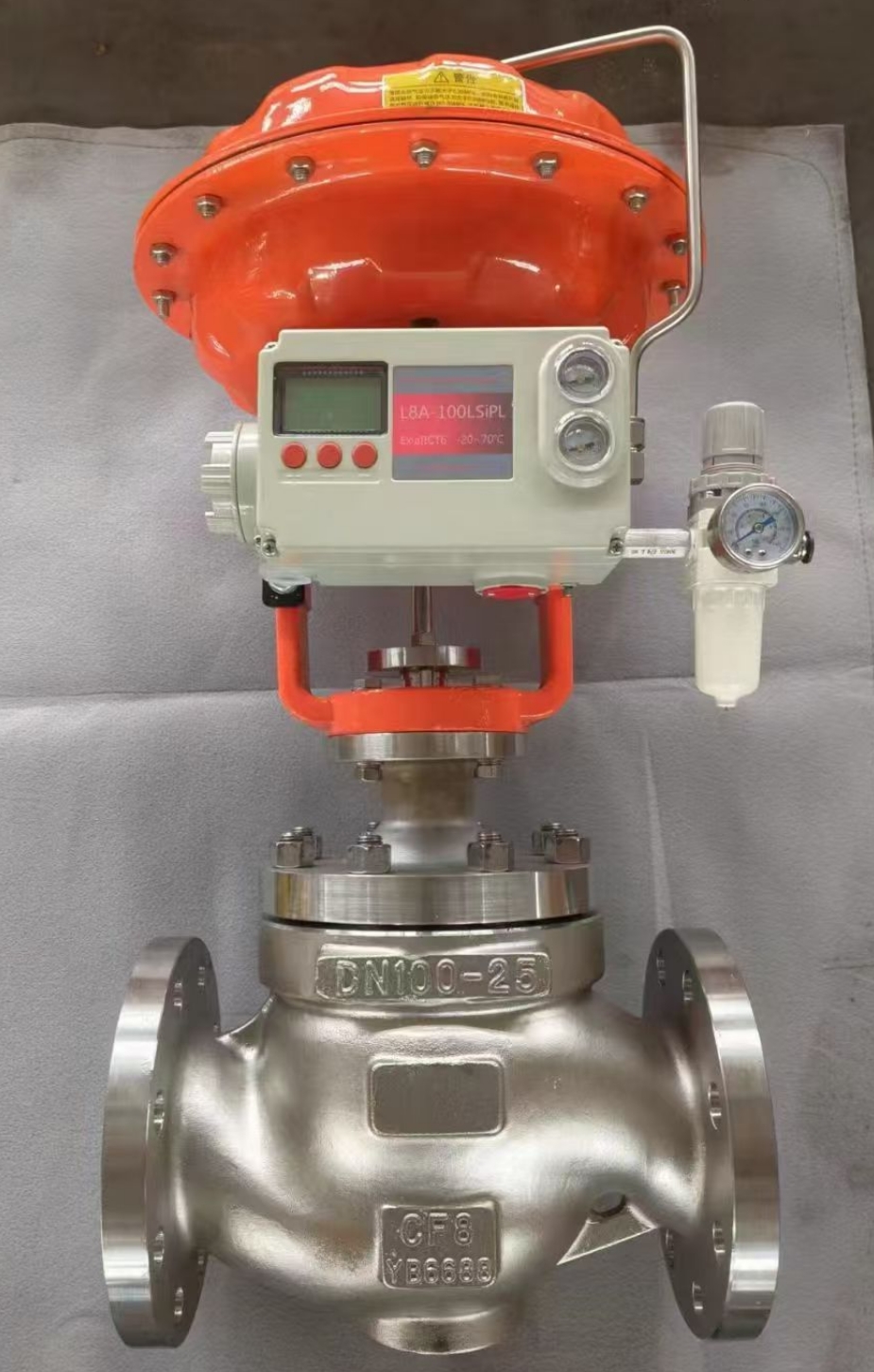
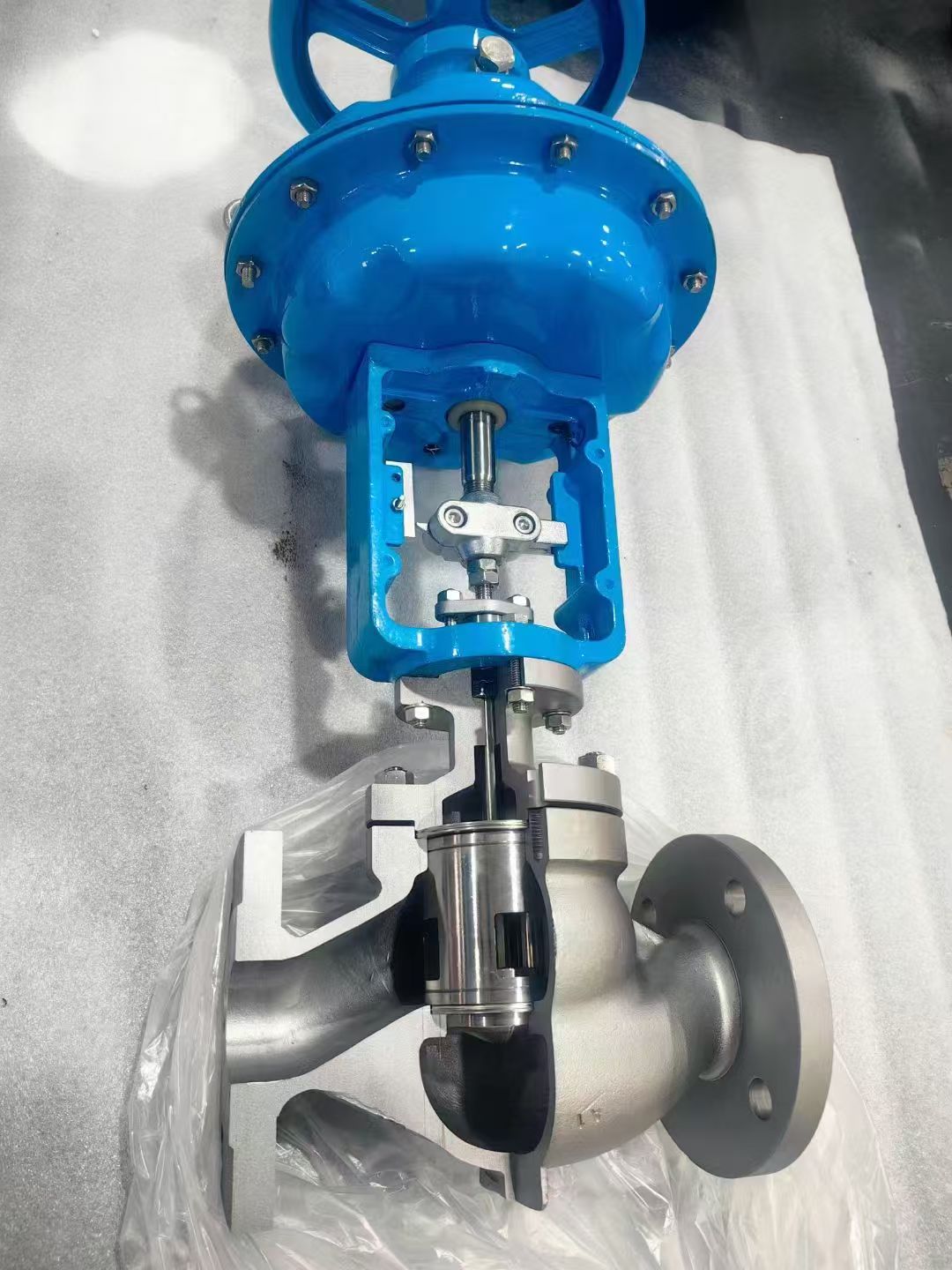
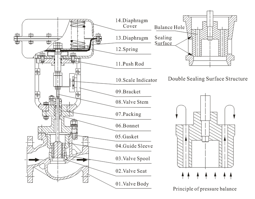
ZJHM Pneumatic cage control valve performance
|
Pneumatic control valve Flow characteristic |
Linear, percentage, quick open |
|
|
Allowable range |
50: 1 |
|
|
Rated Cv value |
Percentage CV10~1400 ,linear CV11~1500 |
|
|
ZJHM Pneumatic Cage control valve |
Metal seal:Ⅱgrade(0.5% rated capacity) |
|
|
ZJHM Pneumatic cage control valve Performance |
||
|
Intrinsic error (%) |
±1.0 |
|
|
Return difference(%) |
≤1.0 |
|
|
Dead zone(%) |
≤1.0 |
|
|
Difference from beginning to end point(%) |
±2.5 |
|
|
Rated travel difference(%) |
≤2.5 |
|
ZJHM Pneumatic cage control valve actuator parameter
|
Pneumatic control valve |
Pneumatic diaphragm actuator |
|
ZH23~ZH56 |
|
|
Multi-spring type |
|
|
Usage |
Regulating type, ON-OFF type |
|
Air supply pressure or Power supply voltage |
Air supply pressure (Spring range) |
|
Connector |
Air pipe connector: RC1/4 |
|
Direct action |
Pressure increase, stem descend, valve close. |
|
Reaction |
Pressure increase, stem ascend, valve open. |
|
Input signal |
40~20mA.DC(with positioner) |
|
Lag |
≤1%FS(with positioner) |
|
Linear type |
2%FS(with positioner) |
|
Environmental temperature |
-10℃~+70℃ |
|
Pneumatic cage guided control valve |
E/P, P/P valve positioner, filter regulator, valve converter, solenoid valve, limited switch |
ZJHM Pneumatic cage control valve technical parameter
Pneumatic cage guided control valve: high capacity Spool(%V、LV)
|
Nominal diameter |
32 |
40 |
50 |
65 |
80 |
100 |
125 |
150 |
200 |
250 |
300 |
350 |
|
|
Seat diameter |
32 |
40 |
50 |
65 |
80 |
100 |
125 |
150 |
200 |
250 |
300 |
350 |
|
|
Rated Cv value |
The percentage of properties |
24 |
36 |
60 |
100 |
140 |
220 |
320 |
420 |
820 |
1000 |
1440 |
1900 |
|
Linear characteristic |
26 |
40 |
75 |
110 |
150 |
240 |
365 |
435 |
850 |
1035 |
1490 |
2000 |
|
|
Rated travel |
25 |
38 |
50 |
75 |
100 |
150 |
|||||||
How does ZJHM Pneumatic cage control valve work?
The regulation process of pneumatic sleeve control valves follows the logical chain of signal conversion-pneumatic drive-mechanical stroke adjustment-sleeve window throttling-fluid parameter stabilization. Its unique pressure balance and sleeve window throttling mechanism fundamentally optimize the stress state and regulation stability of the valve, realizing high-precision and low-jitter fluid regulation under complex working conditions.
1 Signal Receiving and Pneumatic Conversion
The industrial distributed control system (DCS) outputs 4–20mA standard analog electric signals according to the deviation between actual detected parameters and set values. The intelligent valve positioner receives electric signals and converts them into proportional pneumatic pressure signals. The signal pressure corresponds one-to-one with the valve stroke: 4mA corresponds to full closed state, 20mA corresponds to full open state, and intermediate signals correspond to continuous adjustable intermediate openings, realizing stepless stroke control.
2 Pneumatic Drive and Linear Stroke Execution
The converted pneumatic pressure acts on the actuator diaphragm to form stable driving thrust. When the thrust overcomes the reset spring force, packing friction and tiny residual unbalanced force of the medium, the push rod drives the valve stem and plug to move linearly along the sleeve inner wall. Benefiting from the large-area full-wrap guiding structure of the sleeve, the plug runs with high straightness without deflection or swing, ensuring stable and consistent stroke execution.
3 Sleeve Window Throttling and Flow Regulation
Different from the plug-seat gap throttling of single-seat valves, the sleeve valve relies on the overlap area change of sleeve window and valve plug to adjust flow. When the plug rises, the effective overlapping area of the throttling window increases, and the medium flow rate rises; when the plug descends, the window shielding area increases, the flow area decreases, and the flow rate drops. The precisely designed window contour ensures that the valve strictly follows the preset linear, equal percentage or quick-opening flow characteristics during full-stroke regulation.
4 Dynamic Pressure Balance Principle
The core technical advantage of the sleeve valve lies in the built-in pressure balance structure. A pressure balance hole is designed on the valve plug or the upper cavity of the valve body, making the medium pressure of the inlet and outlet channels act on the upper and lower ends of the plug simultaneously. Most of the medium unbalanced force is offset, and only a tiny pressure difference remains for stroke adjustment. This mechanism greatly reduces the actuator load, enables the valve to operate stably under high differential pressure up to PN160 and above, and avoids the problems of difficult valve opening and closing and inaccurate regulation existing in ordinary single-seat valves under high pressure difference.
How to select ZJHM Pneumatic cage control valve?
Scientific and reasonable type selection is the premise to give full play to the performance advantages of pneumatic sleeve control valves. In engineering design, working condition parameters, medium characteristics, control precision and safety requirements need to be comprehensively considered to select matching valve specifications and structural types.
1 Working Condition Parameter Matching
Determine the valve nominal diameter, pressure grade and stroke range according to pipeline design flow, working pressure, working temperature and differential pressure. Take the flow coefficient (Cv value) as the core basis to ensure that the valve operates in the optimal 30%–70% stroke range under rated working conditions, avoiding long-term small-opening vibration and full-opening saturation. For high-differential-pressure working conditions above PN64, priority shall be given to fully balanced sleeve structure to ensure stable valve action and accurate regulation.
2 Medium Characteristic Adaptation
Select structural form and sealing materials according to medium attributes. For clean and low-temperature media such as water and gas, standard balanced sleeve valve with PTFE soft seal is selected; for high-temperature steam and high-pressure oil media, metal hard seal and high-temperature resistant alloy sleeve structure are adopted; for corrosive media such as acid and alkali, 316L stainless steel or fluorine-lined anti-corrosion structure is matched; for media with tiny impurities, enhanced filtering measures and wear-resistant sleeve materials are configured.
3 Control and Safety Requirement Matching
Select flow characteristics according to process regulation requirements: equal percentage characteristic for most pressure and flow precision regulation, linear characteristic for liquid level and fixed-value control, quick-opening characteristic for on-off interlock working conditions. Determine the fail-safe mode according to safety interlock logic: fail-close type for dangerous media to prevent leakage accidents, fail-open type for circulating heat exchange systems to prevent equipment dry burning. Match intelligent positioner, filter regulator and limit switch accessories according to DCS system signal types and remote monitoring requirements.
ZJHM Pneumatic cage control valve daily maintenance
First, air source system maintenance: Regularly drain water and clean the air filter regulator to ensure dry and impurity-free compressed air supply, prevent moisture and particle impurities from blocking the positioner air circuit and wearing the actuator diaphragm. Second, internal component inspection: Periodically check the matching gap between the sleeve and the plug, clean residual tiny impurities, and avoid jamming caused by dirt accumulation. Third, sealing performance maintenance: Regularly inspect the packing box and flange sealing parts for air and medium leakage, replace aging packing in time, and ensure overall tightness. Fourth, regular precision calibration: Calibrate the valve stroke and positioning accuracy quarterly to eliminate regulation errors caused by component wear and aging.
2 Common Faults and Solution Strategies
Insufficient stroke and inaccurate positioning: Mainly caused by positioner calibration deviation, insufficient air source pressure or slight jamming between sleeve and plug. The solutions include recalibrating the intelligent positioner, adjusting the air source pressure to the rated range, and disassembling and cleaning the sleeve and plug matching surface.
Slow valve response and action lag: Caused by blocked positioner air circuit, aging and air leakage of actuator diaphragm or unsmooth valve stem movement. It is necessary to clean the air circuit pipeline, replace aging diaphragms, and lubricate and polish the valve stem.
Medium leakage after closing: Internal leakage is mostly due to wear and scratch of sleeve window and plug sealing surface, which requires grinding treatment or replacement of internal valve trim; external leakage is caused by aging sealing accessories and loose flange bolts, which can be solved by replacing seals and fastening connecting parts.
Abnormal vibration and noise during operation: Mostly occurring in high-differential-pressure working conditions, caused by excessive local flow velocity and turbulent flow. The solution is to check whether the valve stroke is in the optimal working range, and replace the low-noise sleeve structure for long-term high-noise working conditions.
Pneumatic jacket control valve
ZJHM Pneumatic cage control valve
ZJHP Pneumatic single seat control valve
PN25 25 Bar Flanged end solenoid valve
30Bar 3MPa Water flanged solenoid valve
42MPa 420Bar High Pressure Solenoid Valve
PN250 250Bar 25Mpa Solenoid Valve
200Bar 20Mpa 304SS 316SS Solenoid Valve
Address :No.720 Suide Road,Jiading district,Shanghai,China
Tel:+86-17717520739
Wechat:17717520739
Email:info@shxvalve.com



 微信扫一扫 添加我为好友了解更多  |
