control valve,Electric contrPneumaticol valve,Pneumatic ball valve-Control valve manufacturer

contact us

SHANGHAI HUIXUAN VALVE

Mobile:+86-17717520739
Wechat:17717520739
Email:info@shxvalve.com

Address: NO.720, Suide Road, Jiading District,Shanghai, China.
 

Control Valve Manufacturer and Supplier

2022-11-06

Control valve manufacturer and supplier for electric control valve, motorized control valve, pneumatic control valve, temperature control valve, pressure control valve, flow control valve and liquid level control valve for automatic control system. The control valve is the last control component that is used the most frequently in process control sectors. To counteract the load disturbance and maintain the regulated process variable as close to the intended set point as feasible, the control valve modifies a flowing fluid, such as gas, steam, water, or chemical compounds. 

What is A Control Valve?

The control valve is used for controlling fluid flow by changing the size of the flow passage according to the controller and enabling direct control over the flow rate. This results in controlling process quantities such as liquid level, temperature, and pressure. In automatic control terminology, it is called the final control element. Based on controller input, control valve is able to control fluid flow rates.
 
Control valve can be used to regulate pressure and/or flow rate automatically, no matter which pressure is used. In some cases (as determined by design), different plant systems may operate at pressure and temperature combinations that require Class 300 valves, so all control valve is usually Class 300 for interchangeability. As long as the system does not exceed the rating for the Class 150 valves, this is not necessary.

Control valve is normally globe valve whose ends are flanged to facilitate maintenance. Depending on the type of supply, the disk can be moved by hydraulic, pneumatic, mechanical, or electrical actuators. A control valve modulates flow by moving a valve plug in relation to the valve body’s port(s). Control valve plugs are attached to valve stems, which, in turn, are attached to actuators.

Although certain other intrinsic valve features, including parabolic, modified linear, or hyperbolic, are occasionally employed, quick opening, linear, and equal proportion valves are the most often manufactured. Each application’s installation will have a special feature that links fluid flow to heat demand.

Control valve, control valve manufacturerControl valve, control valve manufacturer


How Does A Control Valve Work?

The working principle of control valve is opening or closing internal passages in order to regulate the flow of a liquid or gas. Control valves are part of a control loop that controls a process. Control valve adjusts internal openings in response to instructions from the controller.The process control industry includes control valves as the final control element. Control valve manipulates fluids, such as water, gas, steam, or chemical compounds, to compensate for load disturbances, keeping the regulated process variable as close to the desired set point as possible.

Typically, automatic control valve is opened or closed by electrical, hydraulic, or pneumatic actuators. When a modulating valve can be set anywhere between fully closed and fully open, valve positioners are normally used to ensure that the valve achieves the desired degree of opening.The simplicity of air-actuated control valve makes them popular, as they are only powered by compressed air, as opposed to electrically-operated valves, which require additional cabling and switch gear, and hydraulically-actuated valves, which require high-pressure fluid supply and return lines.

Control signals for pneumatic systems are typically based on a pressure range of 3 to 15 psi (0.2 to 1.0 bar) or, typically, on a 4-20mA electrical signal for industry or a 0-10V signal for 
HVAC systems. Today, electrical control often includes a smart communication signal that can be superimposed over the 4-20mA control signal, allowing the controller to monitor and signal valve health and position back to the controller.

One of the most important but also most neglected parts of a control loop is the control valve. Most of the problem comes from instrument engineers’ limited knowledge of facets, terminologies, and areas of engineering disciplines such as metallurgy, fluid mechanics, noise control, and plumbing, as well as vessel design, which may be involved depending on the severity of the service requirements.

Control loops usually consist of a process condition sensor, a transmitter, and a controller that compares the received “process variable” to the “set point,” i.e. desired process condition. The controller, in turn, transmits a corrective signal to the “final control element,” the last component of the loop and also the “muscle” of the process control system. 

A control loop is considered to be made of three parts, the eyes, which are sensors of the process variables; the brain, which is the controller; and the hands, which are the final control element. Consequently, it is the most vital, but sometimes least understood, component of an automatic control system. In part, this occurs since we are so enamored with electronic components that we neglect to fully understand and utilize all-important hardware elements.

How Does A Control Valve WorkHow Does A Control Valve Work


Control Valve Action

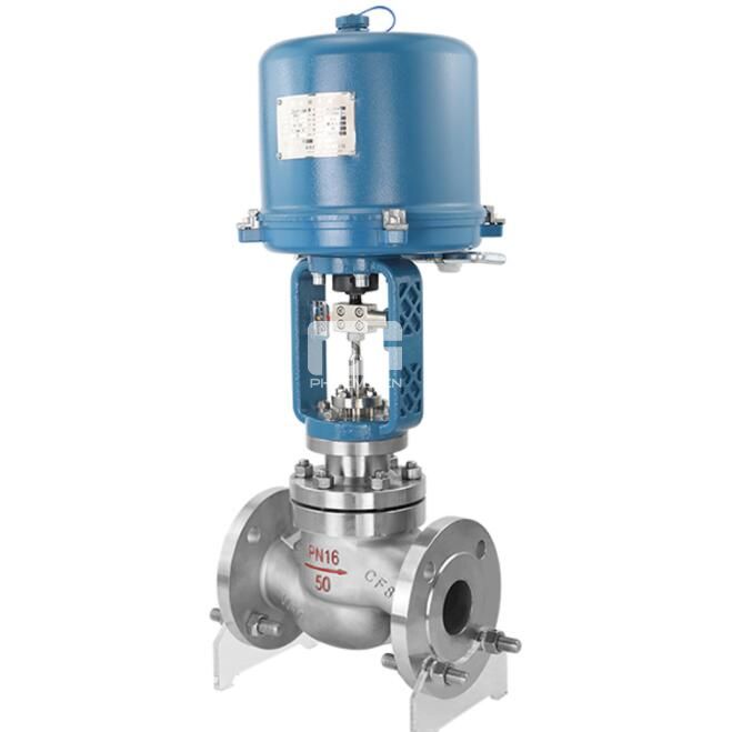
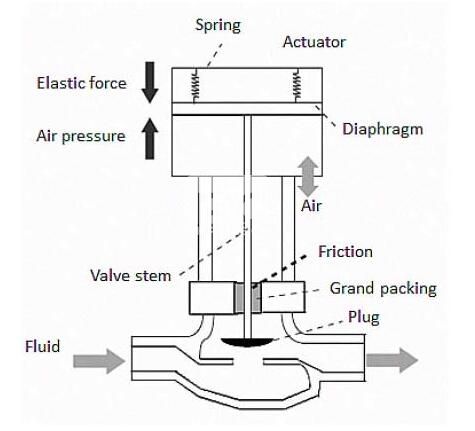
Using an air-operated control valve as an example, there are two control actions available:

“Air or current to open”: As the control signal value increases, the flow restriction lowers.

“Air or current to close”: The flow restriction rises as the control signal value increases.

Failure to safety modes can also occur:

Failure of an air or control signal to close “- If the compressed air supply to the actuator fails, the valve closes under spring pressure or with backup power.

Failure of an air or control signal to open “- If the compressed air to the actuator fails, the valve opens by spring pressure or by backup power.

The types of failure operation are required by the plant’s failure to safety process control specification. In the case of the cooling water, it may fail open, whereas it may fail closed in the event of chemical delivery.
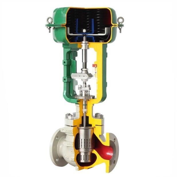
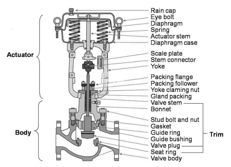

Control Valve Action Parts

 Body 

Control valve body contains the modulating element, such as a plug, globe, ball, or butterfly. There are two basic types of valves; plug and seat valves, where the plug is closed against the seat, or quarter-turn valves that have a disc, ball, or cone turning against the seat.
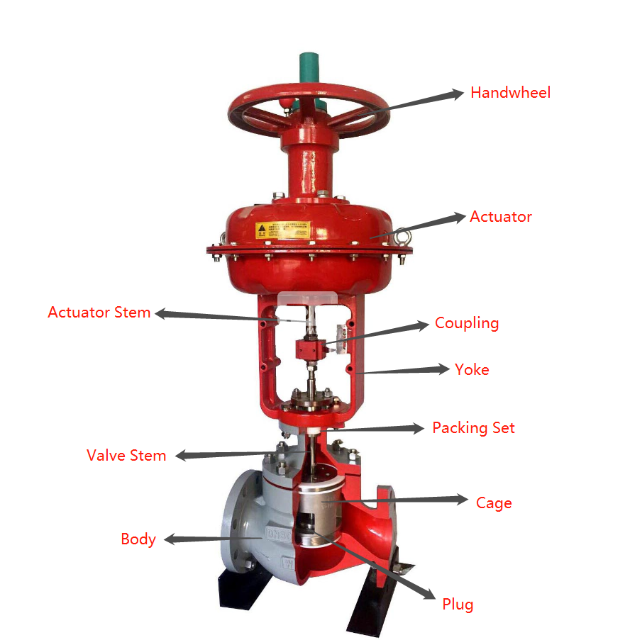
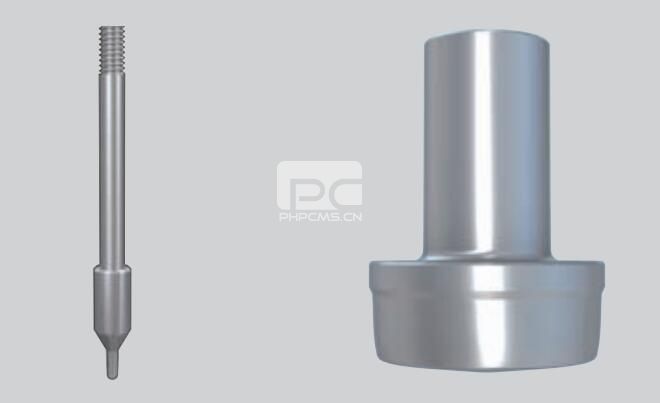
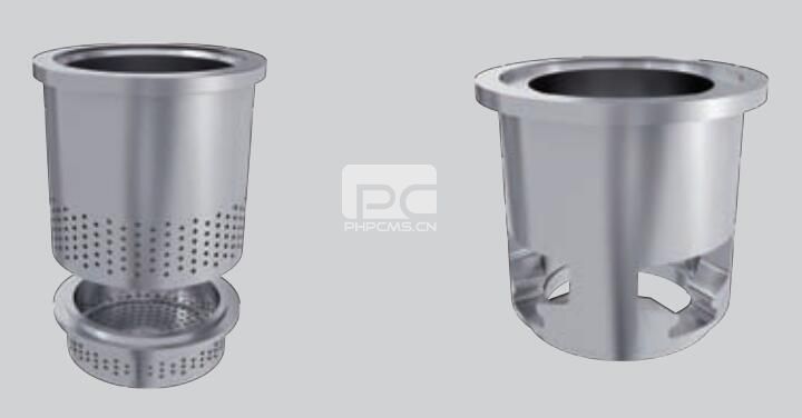
Control valve, control valve manufacturer

Trim 

It is the valve trim that is responsible for regulating the flow of water. There is a fixed-in-place seat along with a moveable plug, disc, ball, or cone. Various passage shapes can be created using the trim, which manages the flow in a deliberate manner.

Control valve, control valve manufacturer

There are three main types of control valve trim:

Snap Trim (also known as Quick-Opening Trim) 

Snap Valve Trims open quickly and are used for on/off operation. Among the common applications are liquid dumps, pressure reliefs, and metering. Zirconia seats are also available for erosive applications.

Nominal Trim (also known as Linear Trim) 

Typically, nominal valve trim is used to throttle liquids, control liquid level, and prevent water hammering.

Equal Percentage Trim 

The equal percentage valve trim is used in throttling applications to control the flow or the pressure of gas and vapor.
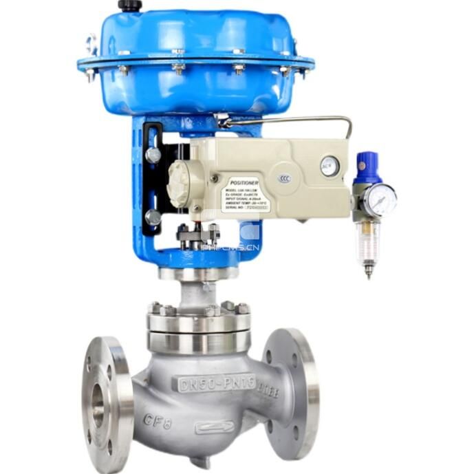
Control valve, control valve manufacturerControl valve, control valve manufacturer

Positioner 

This device ensures that the valve has been opened to the desired degree. Friction and wear problems are thus eliminated. Positioners have the function of delivering pressurized air to the valve actuator to set the valve’s stem or shaft corresponding to a set point in the control system. A positioner is typically used when throttling is required. 

Positioners are designed to take position feedback from the stem or shaft of a valve and deliver the pneumatic pressure to an actuator to open and close the valve. This positioner must be attached to or close to the control valve assembly. 

Positioners are categorized according to types of control signals, diagnostic capabilities, and communication protocols, including pneumatic, electric, electro-pneumatic, and digital.

Pneumatic Valve Positioner 

A pneumatic device sends and receives pneumatic signals. It is intrinsically safe and can close valves with a lot of force.

Using a single-acting valve actuator with range springs, a single-action (or a three-way) pneumatic positioner sends air to and exhausts air from only one side of the valve. However, double-acting or four-way pneumatic positioners can move air on both sides of the actuator.

Electric Valve Positioner 

Electrical signals are sent and received by electric valve positioners. Electric motors can be either single-phase or three-phase run on alternating current (AC) or direct current (DC).

Electro-pneumatic Valve Positioner 

Current control signals are converted into pneumatic equivalents by electro-pneumatic valve positioners.
 

Control Valve Action Arrangement

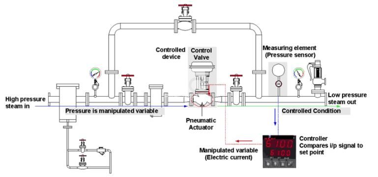
The following image illustrates how the flow rate in a line can be controlled using a control valve. A “controller” receives pressure signals and compares them with the desired flow. If the actual flow varies from the desired flow, the control valve adjusts to overcome the difference. It is possible to control any one of a number of process variables in a similar manner. The most commonly controlled variables are temperature, pressure, level, and flow rate.

Control Valve Action Arrangement


INQUIRY US

微信扫一扫

添加我为好友了解更多